


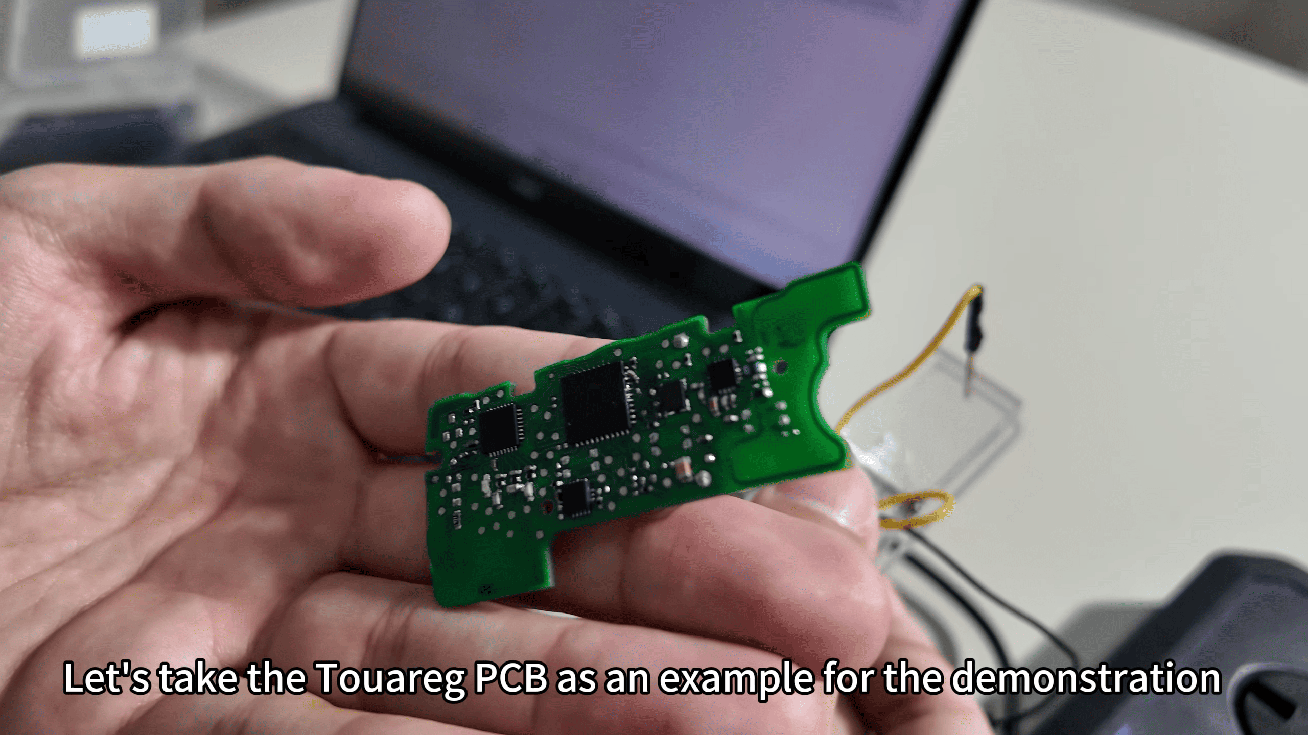
This guide explains how to use KEYDIY KD-MP soldering-free clip to read and program MLB-series PCBs, using two ROG PCBs as an example. The procedure emphasizes correct clip placement, wiring-harness connection, and following the MLB wiring diagram to avoid damage and ensure reliable data collection.
Procedure
1. Prepare: Open the KD-MP package and the PC-side software. Access the MLB interface and click Wiring Diagram to locate the exact wiring layout for your board.
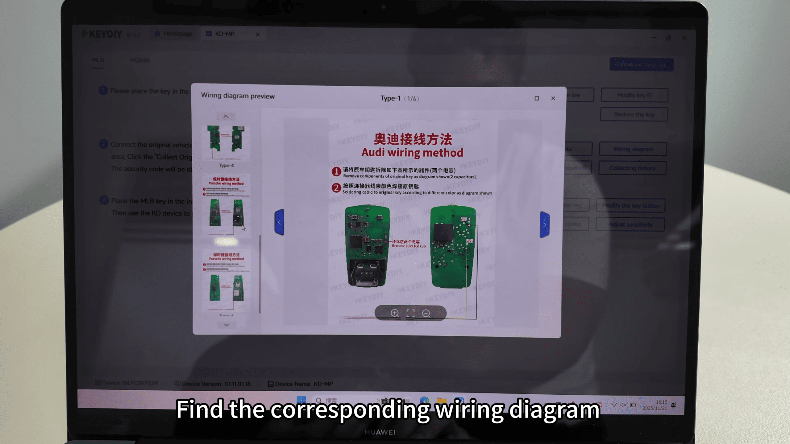
2. PCB prep: Identify the two capacitors marked in the diagram (red boxes). Remove those capacitors as instructed to make the clip contacts accessible.
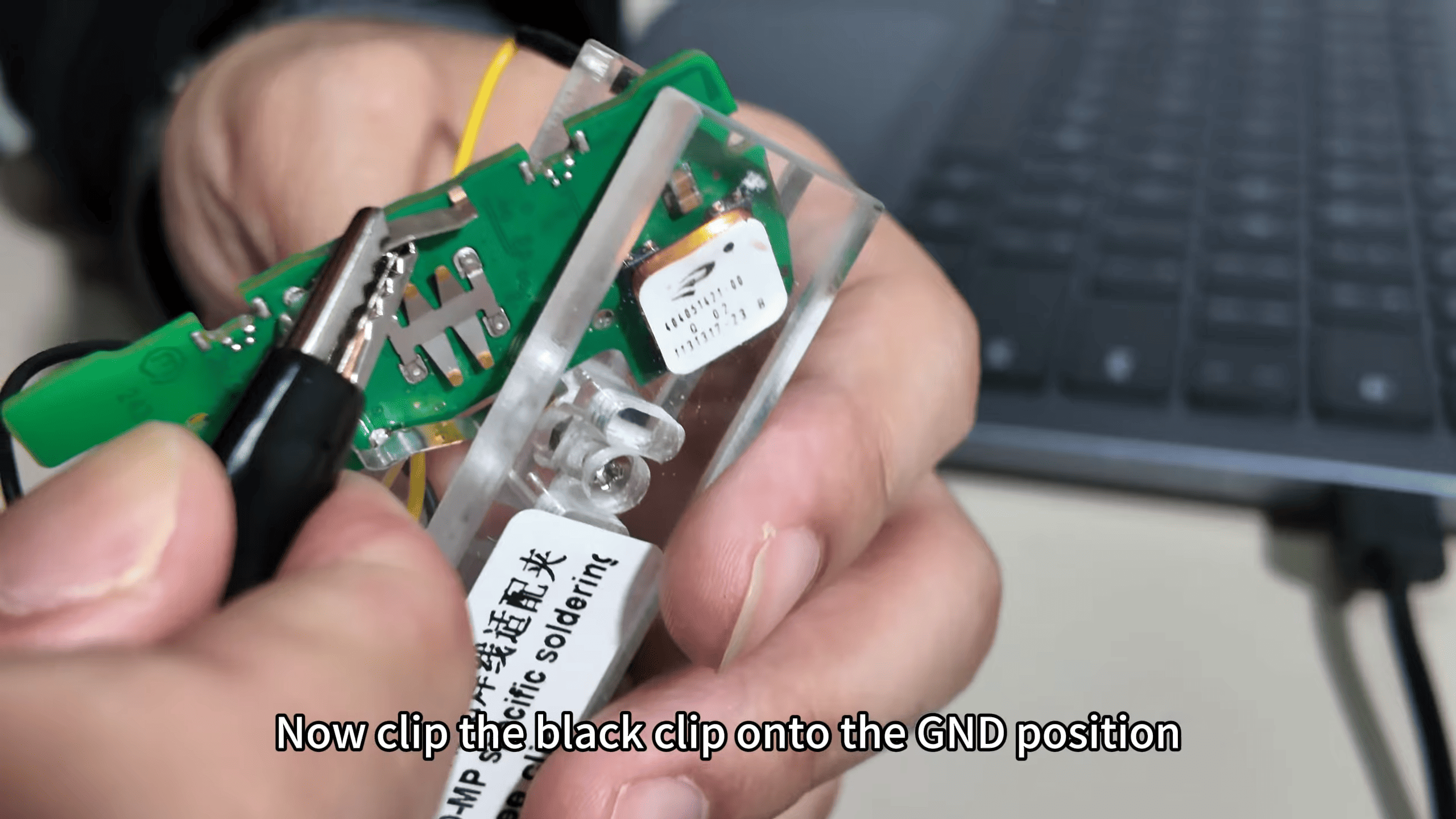
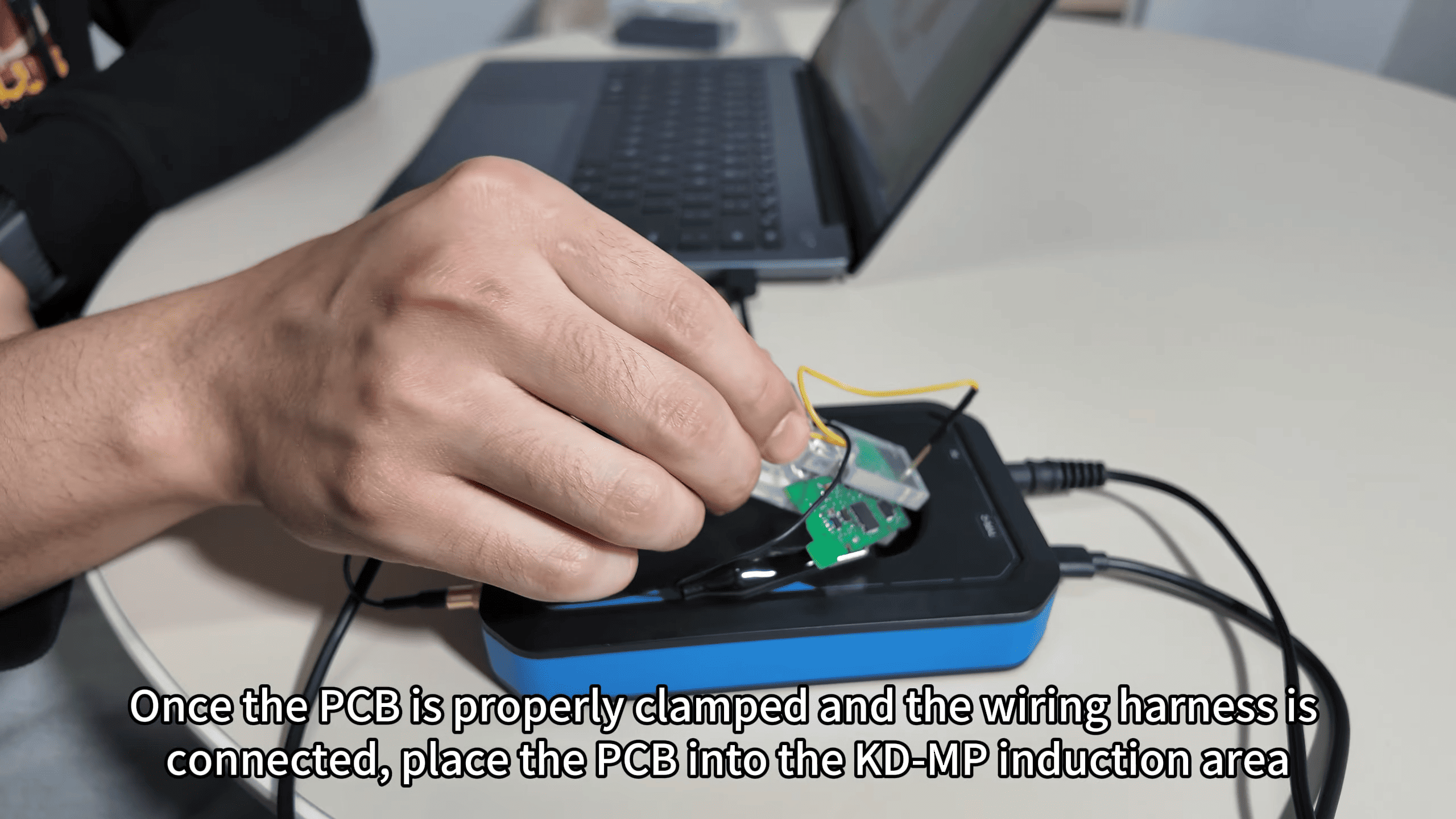
3. Clip placement: Clip the pin for VCC onto the VCC pad first, then attach the black clip to the GND pad. Confirm mechanical stability before proceeding.
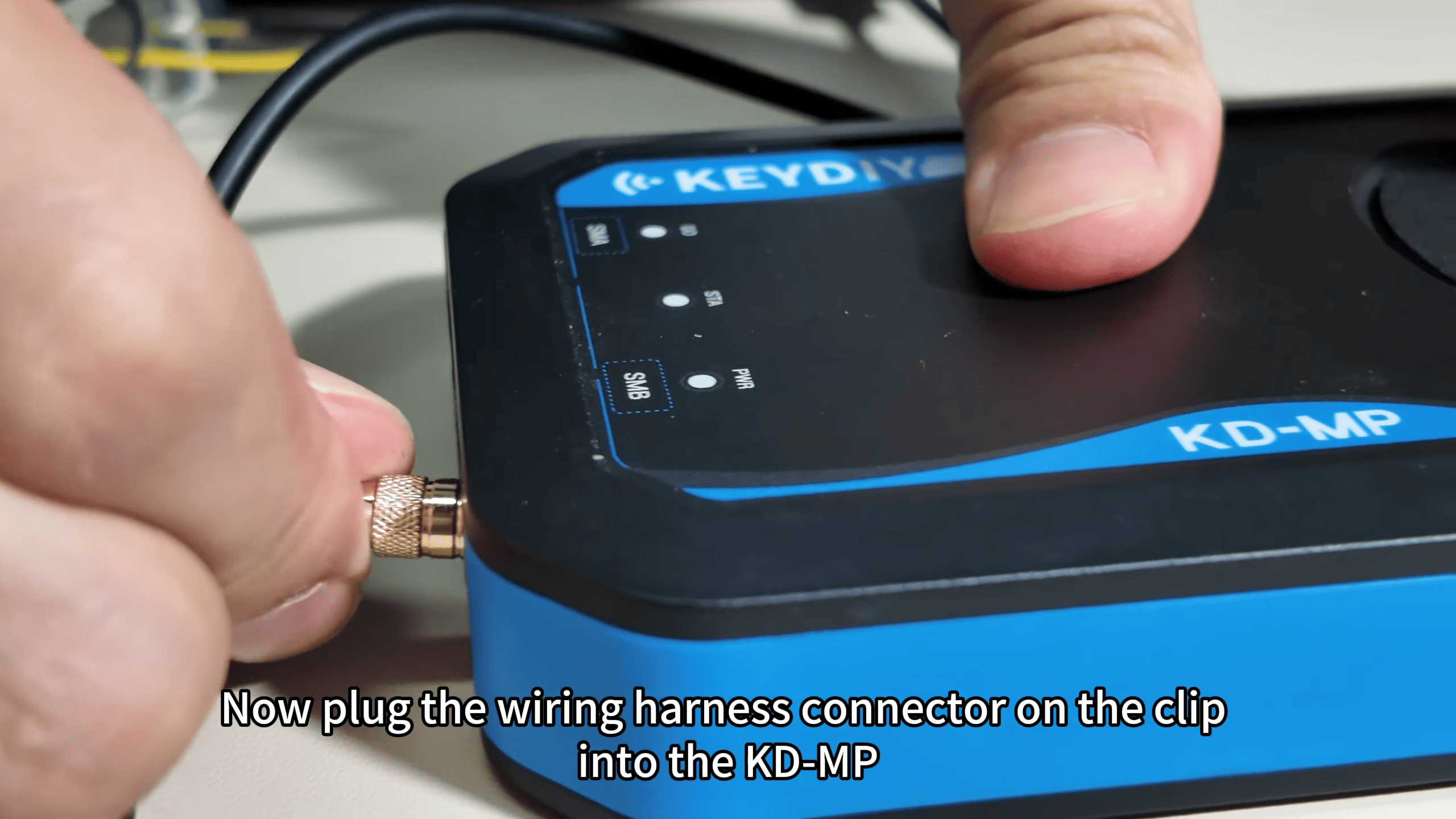
4. Connect harness: Plug the wiring harness connector from the clip into the KD-MP programmer unit. Ensure the cable routing is neat and the clips are secure.
5. Positioning: Place the clamped PCB into the KD-MP induction area so the unit can detect the board correctly.
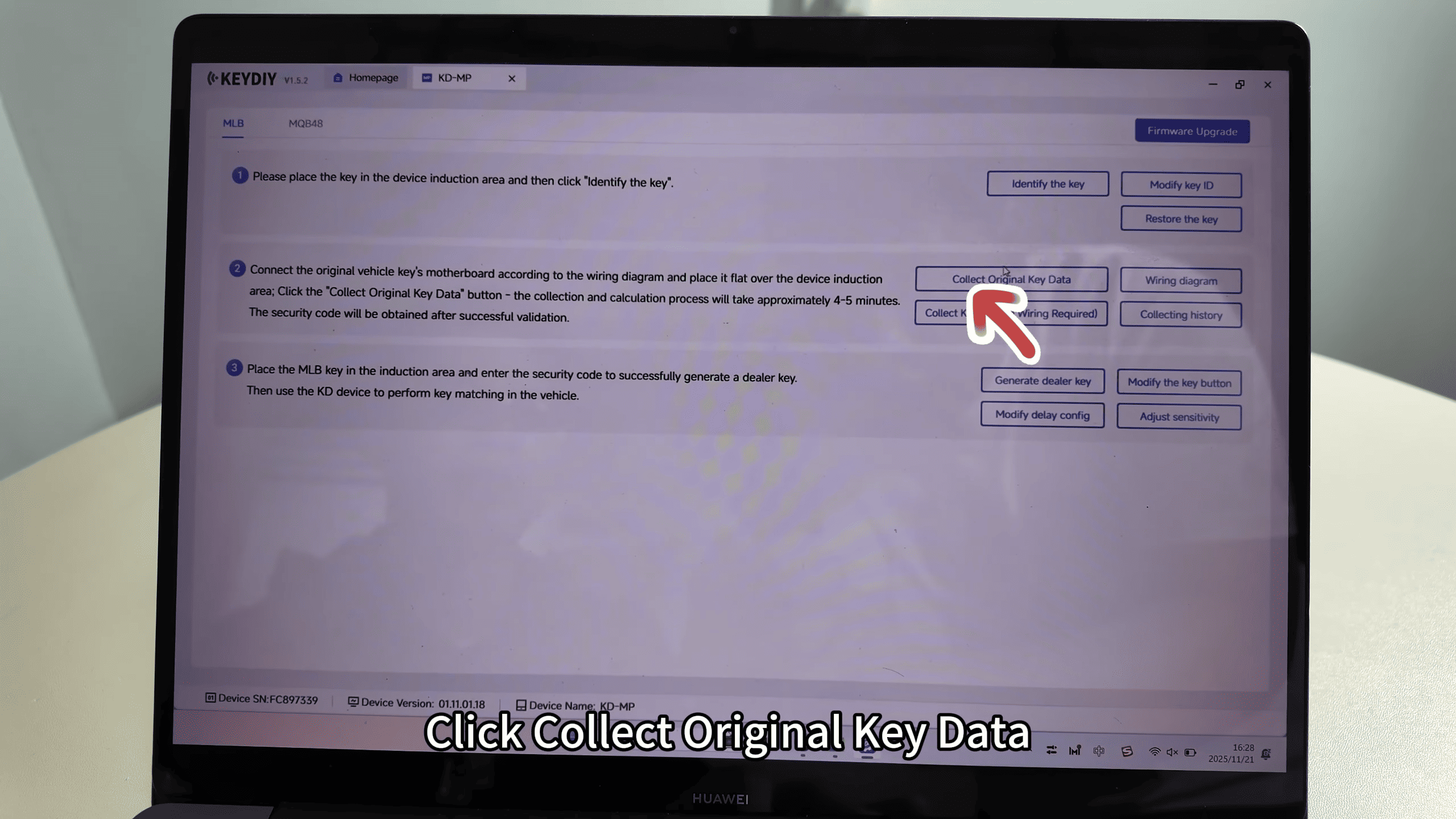
6. Data collection: In the software, click “collect original key data” and follow the on-screen prompts to continue the operation.
Practical tips and warnings
Use a multimeter to verify VCC and GND before clipping to prevent short circuits.
Work on an ESD-safe surface and avoid excessive force when removing capacitors.
If the board shifts, reclamp and revalidate clip contacts before data collection.
Conclusion Following the MLB wiring diagram and the KD-MP clip sequence—VCC first, then GND, harness connection, correct placement in the induction area—allows non‑soldered access to key data. Finally, use the software prompt “collect original key data” to complete the read operation.
Leave a Reply